Rtl Inverter Circuit - Images of Resistor-transistor logic - JapaneseClass.jp / 12v dc to 220/230v ac homemade 500w inverter circuit.
Get link
Facebook
X
Pinterest
Email
Other Apps
Rtl Inverter Circuit - Images of Resistor-transistor logic - JapaneseClass.jp / 12v dc to 220/230v ac homemade 500w inverter circuit.. Table of contents inverter circuit 220v transformer should be used for 220v voltage output. This circuit is wired for 12v rtl operation, and shows rise/fall time around 50ns into 50 ohms. Properties of digital integrated circuits. This inverter circuit converts dc to ac.
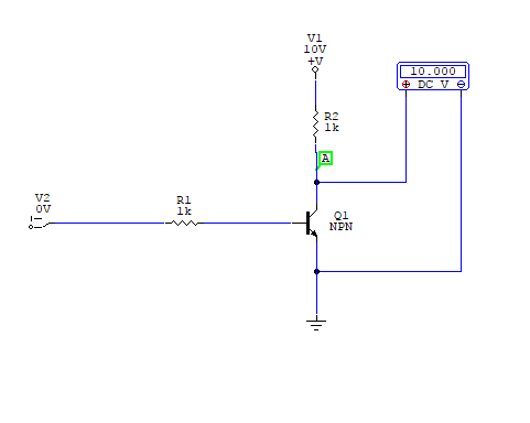
Properties of digital integrated circuits. The basic rtl inverter is the same as the bjt inverter we mentioned earlier. This simple inverter circuit is good for small loads. In this inverter my instructor says that if vin is high, we need m to be in triode to have low voltage in the output. Indiabix provides you lots of fully solved rtl inverter circuit diagram with detailed explanation and working principles.
RTL NOT Gate logic circuit design download - Educative Site from educativesite.com Find all new updated power inveter circuit in here, you can find free for more ideas. This circuit is wired for 12v rtl operation, and shows rise/fall time around 50ns into 50 ohms. Rtl inverter datasheet, cross reference, circuit and application notes in pdf format. We have used easyeda to draw this circuit diagram, and covered a tutorial on 'how to. 1000w power inverter circuit based rfp50n06 mosfet, converting 12vdc battery to become inverter, is an electronic device or circuitry that changes direct current (dc) to alternating current (ac). 220v transformer should be used for 220v voltage output. It has four different operating states which are based on which switches are closed. Design a rtl inverter circuit using h spice simulation tool.
Ltspice circuit models for this project.
This circuit is wired for 12v rtl operation, and shows rise/fall time around 50ns into 50 ohms. 500w modified sine wave inverter. It achieves this by closing and opening the switches in the right sequence. Inverter circuits are among the easiest circuits to build for newbies. Advantage and disadvantage of this three phase inverter circuit. Why doesn't it go to. The basic rtl inverter is actually very similar to the led driver circuit we examined earlier. Table of contents inverter circuit • basic properties of digital integrated circuits • diode digital circuits • bjt digital circuits. These types of inverters better performance, but also relatively simple. Power dissipation of bjt logic circuits. Inverters are the device which converts dc (direct current) to ac (alternating current) simple and powerful pwm inverter circuit diagram designed with ic sg3524 (regulating. This is a simple inverter circuit based upon 13007 transistor.
12v dc to 220/230v ac homemade 500w inverter circuit. A power inverter circuit is a circuit that converts dc power to ac power. Inverters are the device which converts dc (direct current) to ac (alternating current) simple and powerful pwm inverter circuit diagram designed with ic sg3524 (regulating. This inverter circuit converts dc to ac. Indiabix provides you lots of fully solved rtl inverter circuit diagram with detailed explanation and working principles.
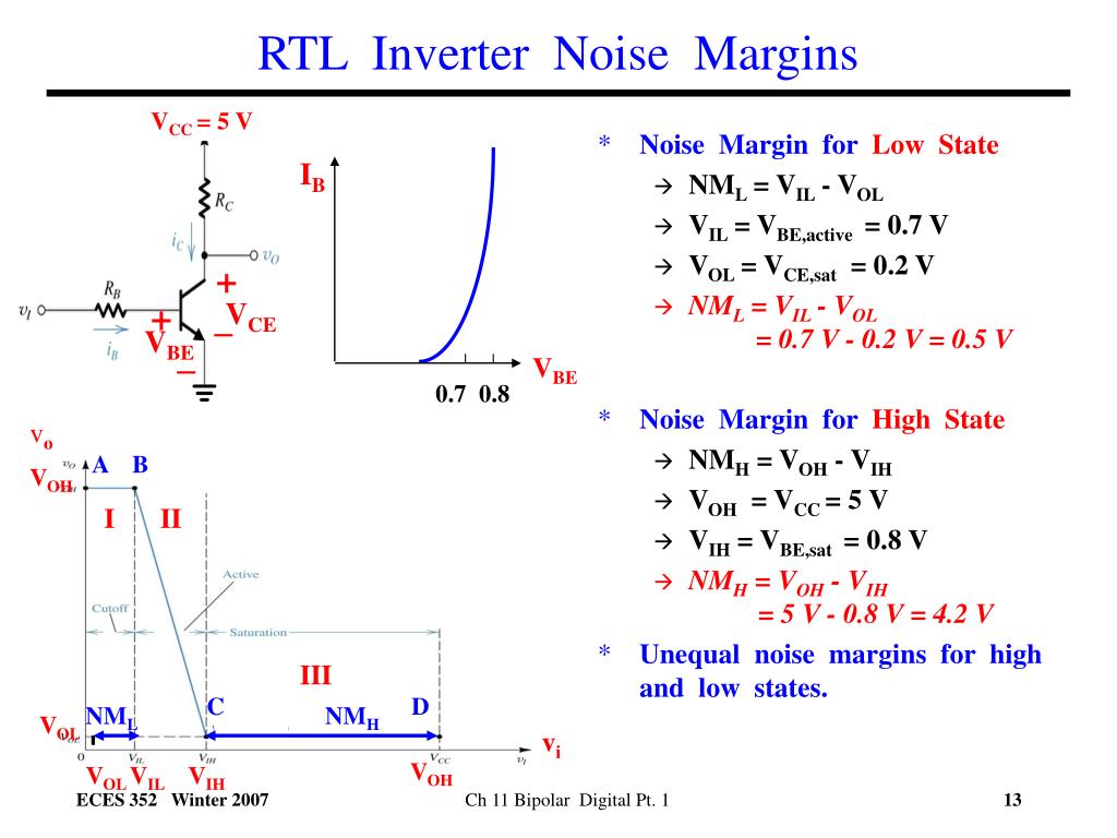
PPT - Ch 11 Bipolar Transistors and Digital Circuits ... from image.slideserve.com Two ic used in this circuit. Vol = n * vce (sat) so: Table of contents inverter circuit • basic properties of digital integrated circuits • diode digital circuits • bjt digital circuits. These types of inverters better performance, but also relatively simple. It has four different operating states which are based on which switches are closed. In this post we discuss the construction of a 5000 watt inverter circuit which incorporates a ferrite in the above simple 12v to 220v ac ferrite inverter circuit we can see a ready made 12v to 310v dc. Design a rtl inverter circuit using h spice simulation tool.
Two ic used in this circuit.
A power inverter circuit is a circuit that converts dc power to ac power. Ltspice circuit models for this project. This simple inverter circuit is good for small loads. Where can i get rtl inverter circuit diagram with explanation? The basic rtl inverter is actually very similar to the led driver circuit we examined earlier. Find all new updated power inveter circuit in here, you can find free for more ideas. Power dissipation of bjt logic circuits. This circuit is wired for 12v rtl operation, and shows rise/fall time around 50ns into 50 ohms. We have used easyeda to draw this circuit diagram, and covered a tutorial on 'how to. This page contain electronic circuits about at category inverter circuit : It achieves this by closing and opening the switches in the right sequence. This circuit is simple and very effective. These types of inverters better performance, but also relatively simple.
The basic rtl inverter is actually very similar to the led driver circuit we examined earlier. The designing parameter the given below (vdd=3v; 1000w power inverter circuit based rfp50n06 mosfet, converting 12vdc battery to become inverter, is an electronic device or circuitry that changes direct current (dc) to alternating current (ac). So far we've played with logic circuits made up of switches to show how various just like other electronic circuits. Circuit diagram of 100 watt dc to ac inverter has been given below.
Motorola - HEP573 - IC, RTL. Hex inverter. from www.electronicsurplus.com Power dissipation of bjt logic circuits. The designing parameter the given below (vdd=3v; Two ic used in this circuit. This circuit is wired for 12v rtl operation, and shows rise/fall time around 50ns into 50 ohms. Where can i get rtl inverter circuit diagram with explanation? In this post we discuss the construction of a 5000 watt inverter circuit which incorporates a ferrite in the above simple 12v to 220v ac ferrite inverter circuit we can see a ready made 12v to 310v dc. So far we've played with logic circuits made up of switches to show how various just like other electronic circuits. 500w modified sine wave inverter.
This inverter circuit converts dc to ac.
Indiabix provides you lots of fully solved rtl inverter circuit diagram with detailed explanation and working principles. The primary difference is that the led driver includes an led in series with the transistor collector lead. Find all new updated power inveter circuit in here, you can find free for more ideas. This simple inverter circuit is good for small loads. Properties of digital integrated circuits. Bipolar equivalent of a cmos inverter stage. Vol = n * vce (sat) so: It achieves this by closing and opening the switches in the right sequence. Where can i get rtl inverter circuit diagram with explanation? Multivibrator cd4047 and opamp comparator lm324 , 6 power transistors are used to. • basic properties of digital integrated circuits • diode digital circuits • bjt digital circuits. This page contain electronic circuits about at category inverter circuit : 1000w power inverter circuit based rfp50n06 mosfet, converting 12vdc battery to become inverter, is an electronic device or circuitry that changes direct current (dc) to alternating current (ac).
So far we've played with logic circuits made up of switches to show how various just like other electronic circuits rtl inverter. In this inverter my instructor says that if vin is high, we need m to be in triode to have low voltage in the output.

Comments
Post a Comment